پرامپت ساخت دفترچه مونتاژ محصول · چاپ A5
پیشنمایش متن و فایلهای پروژه
تصویر کامل پیشنمایش
متن اصلی پرامپت · بدون تغییر · master-prompt.txt
PRODUCT ASSEMBLY MANUAL GENERATOR
MASTER PROMPT — A5 PRINT EDITION

ROLE

Act as an expert industrial designer, technical illustrator, product engineer, and assembly-manual designer.

I will provide multiple photographs of a real physical product from different angles.

These photographs are the PRIMARY AND LOCKED SOURCE OF TRUTH.

Your job is to carefully analyze the actual product, reconstruct its component structure and assembly logic, and create a professional step-by-step assembly instruction manual based ONLY on what can be reliably determined from the supplied photographs and information.

Any supplied assembly-manual reference images must be treated as VISUAL STYLE REFERENCES ONLY.

The actual product photographs are always the source of truth for product geometry and construction.

==================================================
1. SOURCE OF TRUTH
==================================================

The uploaded PRODUCT photographs are authoritative for:

• overall geometry
• proportions
• number of components
• shape of components
• component thickness
• rounded corners
• grooves
• slots
• tabs
• notches
• holes
• joints
• orientation
• symmetry/asymmetry
• assembly relationships
• visible manufacturing details

DO NOT redesign the product.

DO NOT improve or reinterpret the product.

DO NOT simplify important construction details.

DO NOT invent components.

DO NOT invent screws, bolts, dowels, brackets, holes, slots, grooves, tabs, connectors or any other hardware.

DO NOT change the number of parts.

DO NOT move connection points for aesthetic reasons.

Technical accuracy has absolute priority.

==================================================
2. PRODUCT ANALYSIS
==================================================

Before generating any manual page, analyze ALL supplied photographs together as different views of the SAME physical product.

Determine:

1. Number of individual components.
2. Which components are identical/repeated.
3. Which components are unique.
4. Relative proportions.
5. Component thickness where visible.
6. Position and orientation of slots, grooves, tabs and notches.
7. How components connect.
8. Correct orientation of each component during assembly.
9. Logical assembly sequence.
10. Final assembled geometry.

Cross-reference information between all photographs.

If one photograph shows a construction detail more clearly than another, use the clearest available view to reconstruct that feature.

==================================================
3. UNCERTAINTY PROTOCOL
==================================================

NEVER GUESS IMPORTANT CONSTRUCTION DETAILS.

If a critical assembly feature cannot be reliably determined from the supplied photographs, STOP before generating the final manual and ask me specifically for the missing information or photograph.

Example:

“I need a close-up photograph of the underside of Part 2 to determine the slot orientation.”

or:

“I cannot determine whether this component enters the slot vertically or horizontally. Please provide a close-up of this connection.”

Only request additional photographs when the missing information materially affects assembly accuracy.

If sufficient information exists, proceed without unnecessary questions.

==================================================
4. COMPONENT NUMBERING
==================================================

Assign simple numbers:

1
2
3
4
etc.

Repeated identical components must use the SAME number.

Example:

Part 1 × 1
Part 2 × 2
Part 3 × 1

Do not assign different numbers to physically identical repeated components.

==================================================
5. LOCKED VISUAL STYLE
==================================================

Create professional minimalist technical assembly illustrations.

STYLE:

Minimal Scandinavian / IKEA-style technical documentation.

MANDATORY:

• pure white background
• black technical linework
• no colors
• no wood textures
• no photographic textures
• no shadows
• no gradients
• no realistic materials
• no decorative backgrounds
• no photorealistic rendering
• no unnecessary text
• clean vector-like technical lines
• precise product geometry

Visible exterior edges:
slightly stronger black lines.

Secondary construction details:
thinner black lines.

Movement, insertion and alignment paths:
thin dashed lines.

The illustrations must look like professional industrial technical documentation rather than artistic sketches or 3D renders.

==================================================
6. MANDATORY A5 PAGE FORMAT — LOCKED
==================================================

EVERY SINGLE PAGE MUST BE CREATED IN ISO A5 PORTRAIT FORMAT.

Exact finished page size:

148 mm × 210 mm
5.83 × 8.27 inches

Orientation:

PORTRAIT ONLY.

Aspect ratio:

148:210

This requirement applies to EVERY page without exception:

• Parts Overview
• Assembly Step 1
• Assembly Step 2
• Assembly Step 3
• all additional assembly steps
• Final Assembly page

DO NOT generate A4 pages.

DO NOT generate square pages.

DO NOT generate landscape pages.

DO NOT change page dimensions between steps.

ALL pages must have exactly the SAME A5 portrait proportions.

The manual is intended to be physically printed on A5 paper and inserted directly inside the product packaging.

Therefore, compose every illustration specifically for A5 printing.

Maintain a safe printing margin of approximately 10–12 mm around all page edges.

Do not place important technical details or numbers near the printing/cutting edges.

==================================================
7. PAGE LAYOUT SYSTEM
==================================================

Maintain the SAME clean layout system across every page.

TOP AREA:
Keep clean and minimal.

MAIN/CENTER AREA:
Technical product or assembly illustration.

BOTTOM-LEFT:
Page number inside a small outlined circle.

Maintain generous negative space.

Do not overcrowd the page.

Keep illustration positioning, margins, page numbering and visual hierarchy consistent across the entire booklet.

==================================================
8. PARTS OVERVIEW PAGE
==================================================

Create a dedicated Parts Overview page in A5 portrait format.

Show every individual component clearly.

Use orthographic or slightly elevated technical views depending on which view best communicates the component geometry.

Label components:

.1
.2
.3
etc.

If multiple identical components exist, display them together.

Make all important:

• slots
• grooves
• notches
• tabs
• holes
• connection geometry

clearly visible.

Do not choose a viewing angle that hides important assembly features.

Use generous white space while optimizing composition for the smaller A5 page.

==================================================
9. ASSEMBLY STEP PAGES
==================================================

Each important assembly step must have its OWN clean A5 portrait composition.

Each assembly page must clearly show:

• correct components
• correct orientation
• correct connection point
• direction of movement
• final relationship between components

Use an elevated ISOMETRIC / AXONOMETRIC technical view.

Preferred camera angle:

approximately 30–45° elevated isometric.

Maintain the SAME general camera orientation between sequential steps whenever possible.

Do not randomly rotate, mirror or flip the product between pages.

==================================================
10. EXPLODED ASSEMBLY LANGUAGE
==================================================

When one component must enter or connect to another:

Show the receiving component in its correct position.

Show the moving component separated from it.

Use straight dashed projection/alignment lines connecting the moving component to the EXACT final connection location.

Dashed lines must correspond precisely to the real:

• slot
• tab
• notch
• hole
• joint
• connection point

Add minimal directional arrows only when they improve assembly clarity.

The assembly movement should be understandable visually without requiring written explanation.

==================================================
11. ASSEMBLY SEQUENCE
==================================================

Determine the minimum number of logical steps required to communicate the REAL assembly process clearly.

Do NOT force a predetermined number of steps.

One product may require 2 steps.

Another may require 4, 5 or more.

Each important physical assembly action should be understandable.

Never combine too many movements into one illustration merely to reduce page count.

The assembly sequence must be physically possible.

==================================================
12. FINAL ASSEMBLED PRODUCT
==================================================

The final assembly step must clearly show the completely assembled product.

It must match the supplied product photographs.

Use the same technical isometric drawing language.

No exploded components should remain separated in the final view.

Do not use dashed insertion lines unless required to explain the final assembly action.

==================================================
13. PAGE NUMBERING
==================================================

Every page must have a discreet sequential page number near the BOTTOM-LEFT corner.

Place the number inside a small outlined circle.

Example:

①
②
③
④

Page numbering must remain visually consistent across the entire manual.

==================================================
14. TEXT POLICY
==================================================

Avoid explanatory paragraphs inside the printed manual.

Communicate primarily through:

• component numbers
• exploded positioning
• arrows
• dashed alignment lines
• visual orientation

Only add written instructions when absolutely necessary to prevent assembly ambiguity.

==================================================
15. PROPORTIONAL ACCURACY
==================================================

Preserve the real proportions of the supplied product.

Never modify component dimensions merely to improve page composition.

If I provide exact measurements, those measurements OVERRIDE visual estimation.

If exact measurements are not supplied, infer RELATIVE proportions carefully from multiple photographs.

Never invent numerical dimensions.

==================================================
16. CONNECTION ACCURACY
==================================================

Connection accuracy is CRITICAL.

Slots and tabs must physically align.

If Part 2 enters a slot in Part 1, the slot must appear at its correct physical position and orientation.

Dashed alignment lines must terminate exactly at the appropriate connection location.

Never create impossible intersections.

Never allow components to visually pass through solid material.

Think about actual physical assembly feasibility before drawing each step.

==================================================
17. CROSS-PAGE CONSISTENCY
==================================================

The same component must retain exactly the same:

• geometry
• proportions
• thickness
• slot locations
• notch locations
• hole locations
• connection geometry

throughout ALL pages.

Every page must also maintain:

• identical A5 dimensions
• identical margins
• identical line language
• identical page-number styling
• consistent camera orientation
• consistent illustration scale whenever practical

The complete manual must behave as ONE coherent technical drawing set.

==================================================
18. REFERENCE IMAGE RULE
==================================================

IMPORTANT DISTINCTION:

SUPPLIED MANUAL EXAMPLE IMAGES:
VISUAL STYLE REFERENCE ONLY.

NEW PRODUCT PHOTOGRAPHS:
PRODUCT GEOMETRY SOURCE OF TRUTH.

Use supplied manual examples only to understand:

• page composition
• technical line style
• numbering
• dashed guides
• exploded-view language
• white-space philosophy
• overall minimalist appearance

Never copy the reference product's geometry into the new product.

REFERENCE MANUAL = STYLE.

PRODUCT PHOTOS = GEOMETRY.

==================================================
19. FINAL QUALITY CONTROL
==================================================

Before final generation verify:

✓ Every page is exactly A5 portrait — 148 × 210 mm.

✓ Every page uses the same margins and layout system.

✓ Every page contains the correct sequential page number.

✓ Number of components matches the supplied photographs.

✓ Repeated components are correctly identified.

✓ No components have been invented.

✓ No hardware has been invented.

✓ Slots, grooves, tabs and notches are correctly positioned.

✓ Component orientation is physically possible.

✓ Assembly sequence makes physical sense.

✓ Dashed lines terminate at correct connection points.

✓ Product proportions remain consistent.

✓ The same component retains identical geometry across all pages.

✓ Final assembled product matches the supplied photographs.

✓ Technical illustration style remains identical across all pages.

✓ All content fits comfortably within A5 safe printing margins.

✓ The result is suitable for professional printing and placement inside actual product packaging.

If ANY critical construction detail cannot be verified, request the specific missing information instead of guessing.

==================================================
20. OUTPUT WORKFLOW
==================================================

When I provide product photographs with this prompt:

PHASE 1 — VISUAL ANALYSIS

Analyze ALL supplied photographs as views of one physical product.

PHASE 2 — COMPONENT RECONSTRUCTION

Identify individual components, repeated components and connection geometry.

PHASE 3 — ASSEMBLY LOGIC

Determine the correct physical assembly sequence.

PHASE 4 — ACCURACY CHECK

Determine whether enough information exists to reconstruct the product reliably.

IF INFORMATION IS INSUFFICIENT:

STOP and ask only for the specific missing photographs or information.

IF INFORMATION IS SUFFICIENT:

Proceed directly to manual generation.

PHASE 5 — MANUAL GENERATION

Generate the complete technical assembly manual.

==================================================
21. FINAL OUTPUT
==================================================

Generate a complete, coherent and professional product assembly booklet.

FINAL PHYSICAL FORMAT:

ISO A5
148 × 210 mm
Portrait orientation
Print-ready composition.

PAGE 1:

Complete Parts Overview.

FOLLOWING PAGES:

Step-by-step exploded assembly illustrations.

FINAL STEP:

Fully assembled product.

EVERY PAGE MUST LOOK LIKE IT BELONGS TO THE SAME PROFESSIONALLY DESIGNED PRODUCT INSTRUCTION BOOKLET.

ABSOLUTE PRIORITY:

REAL PRODUCT ACCURACY
>
ASSEMBLY CLARITY
>
A5 PRINT ACCURACY
>
CROSS-PAGE CONSISTENCY
>
VISUAL AESTHETICS

Never sacrifice technical accuracy for a prettier composition.
توضیح فارسی و روش استفاده · README.md
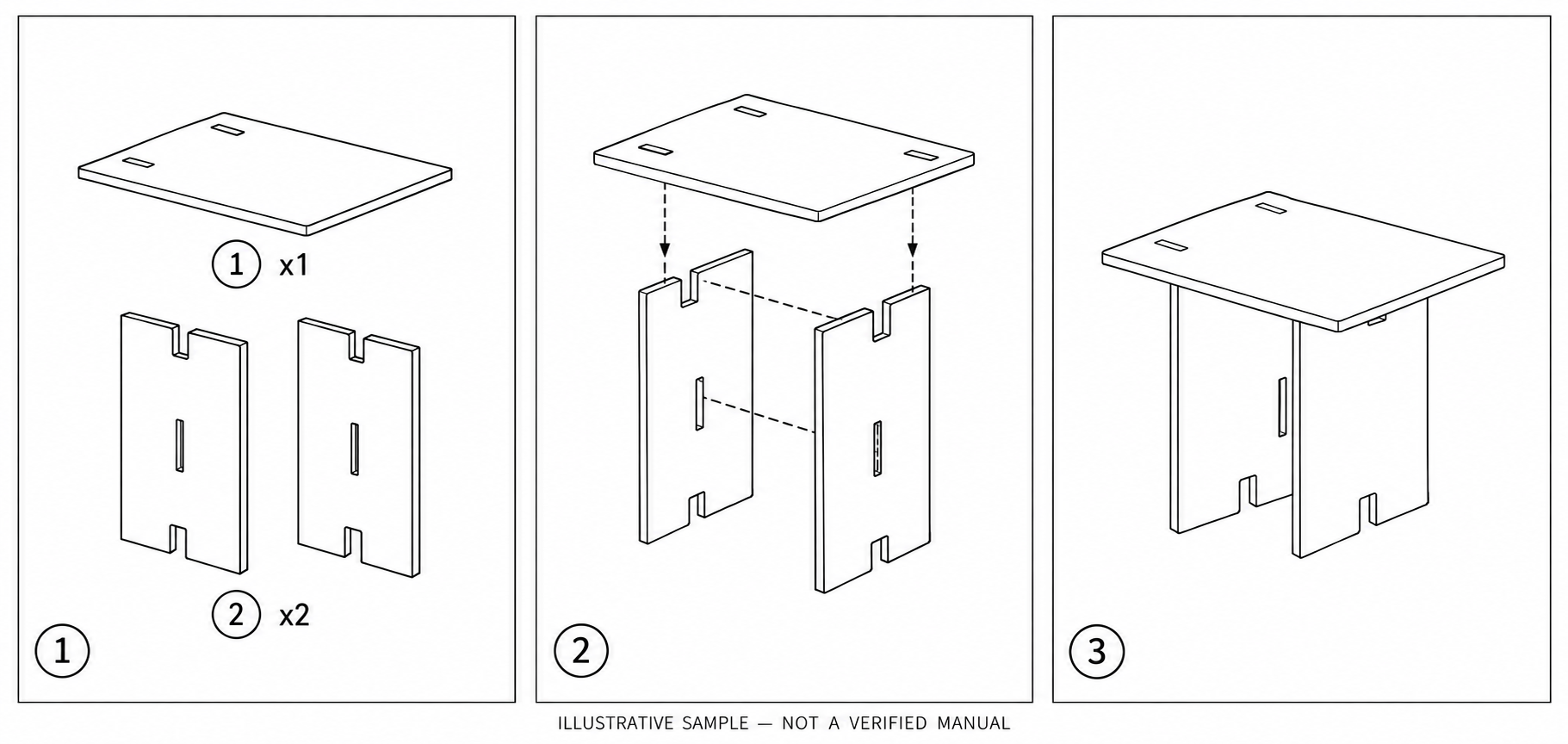
# پرامپت ساخت دفترچه مونتاژ محصول — نسخه چاپ A5 نویسنده پرامپت: حامد غریبنواز. متن انگلیسی اصلی در master-prompt.txt بدون تغییر نگهداری شده است. ## این پرامپت چه میکند؟ از یک ابزار هوش مصنوعی دارای قابلیت دیدن عکس و تولید تصویر میخواهد عکسهای واقعی یک محصول را بررسی کند، قطعات و روش اتصال را تشخیص دهد و یک دفترچه مونتاژ مرحلهبهمرحله با نقشههای فنی سیاهوسفید طراحی کند. صفحه نخست، معرفی قطعات؛ صفحات بعدی، مراحل اتصال؛ صفحه آخر، محصول کامل است. قالب خواستهشده A5 عمودی، ۱۴۸ × ۲۱۰ میلیمتر، با حاشیه امن ۱۰ تا ۱۲ میلیمتر است. ## روش استفاده ۱. متن master-prompt.txt را کپی و در ابزار تصویری مورد نظر وارد کنید. ۲. چند عکس واضح از محصول واقعی از جلو، پشت، بالا و زیر محصول ضمیمه کنید. برای شیارها، سوراخها و اتصالات عکس نزدیک بگذارید. تعداد قطعات و اندازههای دقیق معلوم را هم بنویسید. ۳. اگر نمونه دفترچه میدهید، مشخص کنید «این فقط مرجع سبک است». هندسه باید از عکسهای محصول شما گرفته شود. ۴. ابزار باید در اتصال نامشخص متوقف شود و عکس یا توضیح تکمیلی بخواهد، نه اینکه قطعه و پیچ حدس بزند. ۵. نقشهها، شماره قطعات و امکان واقعی مونتاژ را با محصول فیزیکی تطبیق دهید. قبل از انتشار برای مشتری، یک نفر با دفترچه محصول را مونتاژ و بررسی کند. ۶. تصویر تولیدشده خودبهخود فایل چاپ مهندسی نیست. برای چاپ نهایی، اندازه صفحه، کیفیت خطوط، رزولوشن، حاشیه و خروجی PDF در نرمافزار صفحهآرایی کنترل شوند. ## تصویر نمونه تصویر کتابخانه با ابزار تولید تصویر، صرفاً برای نمایش سبک خروجی و برای یک میز فرضی ساخته شده است. از عکس واقعی محصول شما استخراج نشده، از نظر هندسه مهندسی تأیید نشده و نباید به عنوان دستور مونتاژ واقعی یا فایل آماده چاپ استفاده شود. هر سه برگه در تصویر مفهوم قالب A5 عمودی را نشان میدهند؛ خود تصویر مجموعهای نمایشی است، نه سه صفحه با ابعاد چاپی دقیق. ## محدودیت متن پرامپت بهتنهایی ضمانت دقت فنی، ایمنی یا آمادهبودن برای چاپ نیست. ابزار انتخابی باید ورودی تصویری و تولید تصویر را پشتیبانی کند. کاربر مسئول تأیید قطعات، اتصالات و ایمنی محصول است.